#FPGA Design Assignment Help
Explore tagged Tumblr posts
Visit Tumblr Blog
Explore Tumblr blogs with no restrictions, modern design and the best experience.
Last Seen Tumblr Blogs


Fun Fact
Tumblr has a low social media market share in South America.
Text
Mastering VLSI: Why the Right Training Matters for a Thriving Tech Career
The Rising Demand for VLSI Experts The modern world is driven by electronics. From smartphones to smart cars, every innovation depends on microchips designed using VLSI (Very Large Scale Integration) technology. With the growing use of AI, IoT, and automation, the need for skilled VLSI professionals has increased rapidly. This makes VLSI an essential field for those looking to build a strong career in electronics and semiconductor industries. Choosing the right learning path is key to making the most of this opportunity.
Exploring the Benefits of VLSI Online Training Courses Many learners today seek flexible and effective ways to upskill. VLSI online training courses offer an excellent solution by combining convenience with quality education. These courses provide access to experienced instructors, practical assignments, and industry-based projects—all from the comfort of home. Learners can grasp digital design, physical design, verification, and ASIC/FPGA concepts without sacrificing their job or academic responsibilities. The online model also allows repeated learning and flexible scheduling, making it ideal for beginners as well as professionals wanting to upgrade their knowledge.
Choosing the Right Learning Mode While online learning provides flexibility, some individuals prefer classroom-based teaching for real-time interaction and immediate doubt clearing. The choice between online and offline modes largely depends on individual preferences, learning habits, and career goals. However, what truly matters is the quality of the training and the expertise of the instructors involved.
Key Skills Taught in VLSI Training A well-structured VLSI course should cover areas like CMOS technology, HDL languages such as Verilog and VHDL, physical design flow, and functional verification techniques. Practical exposure through lab sessions or simulation tools is crucial. Additionally, learners should be guided on real-time projects to apply their theoretical knowledge to industry problems.
Why VLSI Coaching in Hyderabad is Gaining Popularity Hyderabad has become a major hub for semiconductor and electronics industries. As a result, VLSI coaching in Hyderabad has gained recognition for producing skilled professionals. Reputed training centers in the city offer tailored coaching with an industry-aligned curriculum, experienced faculty, and placement support. Many aspirants from across the country travel to Hyderabad to benefit from this coaching environment that bridges academic learning with industry demands.
Conclusion VLSI technology plays a vital role in shaping the electronics and semiconductor industries. Whether through VLSI online training courses or classroom-based programs like VLSI coaching in Hyderabad, acquiring the right skills is essential for career growth. Institutions like Takshila Institute of VLSI Technologies provide training that matches industry standards, helping learners succeed in a competitive field. The choice of platform and location may differ, but the goal remains the same—building a strong foundation in VLSI for a successful future.
0 notes
Text

FPGA Assignment Help. FPGA Project Help. FPGA Homework Help
An FPGA (Field Programmable Gate Array) is an integrated circuit that can be programmed by the user after manufacturing to perform specific digital functions. Unlike fixed-function chips, FPGAs contain an array of configurable logic blocks and interconnects that allow designers to create custom hardware circuits.
Some of the important vendors of FPGA are:
Xilinx FPGA (now part of AMD)
Intel (formerly Altera)
Lattice Semiconductor FPGA
Get in touch with us for expert assistance for any FPGA assignment, project or homework. Our solutions are fast and accurate.
Visit our website for more information or email us at [email protected]. You can also ping us on Whatsapp on +1.289.499.9269 for instant support.
0 notes
Text
Top VLSI Institutes in Bangalore and Top 10 VLSI Training Institutes – Takshila Institute
The Takshila Institute of VLSI Technologies in India is recognized as one of the top VLSI institutes in Bangalore, offering industry-focused training for students and professionals aspiring to build a career in Very Large Scale Integration (VLSI) design. With the growing demand for skilled VLSI engineers in the semiconductor industry, high-quality training institutes play a crucial role in bridging the gap between academic knowledge and industry requirements. Takshila Institute of VLSI Technologies stands out as a leading VLSI training provider, offering specialized courses that equip learners with practical skills and real-world experience.
As one of the top 10 VLSI training institutes, Takshila Institute of VLSI Technologies provides comprehensive training programs covering digital design, analog layout, FPGA design, ASIC verification, physical design, and semiconductor fabrication. The curriculum is designed in collaboration with industry experts, ensuring that students gain hands-on experience in EDA tools, RTL coding, verification methodologies, and physical design flow. The institute also offers specialized courses in Verilog, SystemVerilog, UVM, and Python for VLSI, helping students develop expertise in front-end and back-end design.
The top VLSI institute in Bangalore, Takshila Institute of VLSI Technologies, provides state-of-the-art lab facilities, expert faculty guidance, and real-time project work to ensure that students gain practical exposure to modern VLSI design methodologies. The training includes live interactive sessions, hands-on assignments, and industrial case studies, allowing learners to develop a deep understanding of semiconductor technology. The institute focuses on preparing students for job opportunities by offering placement assistance, resume-building support, mock interviews, and internship opportunities.
What makes Takshila Institute of VLSI Technologies one of the top 10 VLSI training institutes is its career-oriented approach and strong industry connections. The institute has a proven track record of placing students in top semiconductor companies, making it a preferred choice for those looking to enter the VLSI industry. Whether you are a fresh graduate, working professional, or career switcher, this institute provides flexible learning options through classroom-based training and online courses.
With a reputation for excellence in VLSI education, Takshila Institute of VLSI Technologies is a trusted name in semiconductor training in India. If you are looking for the top VLSI institute in Bangalore or one of the top 10 VLSI training institutes, Takshila Institute of VLSI Technologies offers the best learning experience to help you succeed in the VLSI industry.
0 notes
Text
VLSI Projects Using Xilinx Software
Very Large Scale Integration VLSI Xilinx software projects entail the construction of circuits that have millions of transistors on a single chip. Xilinx offers encompassing FPGA solutions like Vivado and ISE for VLSI design where end-user can implement his/her digital system with utmost ease at high level of abstraction. Common offerings are usually of the form of ASICs that incorporate digital systems such as processors, memory interfaces, communication interfaces, or specific Circuits. One of the most selected project ideas is to develop an MIPS microprocessor on Xilinx FPGAs for ALU, control units, registers and the like. Another frequently assigned project is the synthesis of the digital signal processing (DSP) system associated with pulsing or graphic processing. Its software includes a programmable logic device programming software, FPGA development software, an integrated circuit/multi-chip module fabrication software, simulation software as well as a hardware verification and timing analysis software that helps confirms that the VLSI design is functional and efficient. These projects are useful in grasping concepts like digital logic, HDL, and the usage of FPGAs to conceptualize electronic systems.
#vlsi#xilinx#software#projects#fpgasoultion#digitalsystem#VLSIdesign#engineeringprojects#takeoffedugroup
0 notes
Text
Faststream Technologies software-interpreted FPGA Design Services are assigned to bring end-to-end system incorporation from design, research, and development to testing for any kind of design specifications. Faststream Technologies has worked on various projects on all major FPGA platforms which entail millions of multi-clock domains, gate designs, and hybrid design applications.
Our expert design team delivers wide FPGA design and development competence to various projects in the domain of High-speed Memory and network interfaces, advanced algorithm development, and embedded software services. As a turnkey product design firm, we design custom FPGA boards and also integrate our FPGA designs with existing client hardware.
Faststream Technologies proposes FPGA-based design & built-up SoC-based design services which add a stack of technologies and interfaces. Our previous designs incorporated soft core processors like Nios II, Microblaze, OpenRISC, etc, and hard processors like multi-core ARM Cortex, PowerPC, etc. Our embedded software development team has supported in bringing up operating systems like Linux and developing drivers for these custom devices. We have even developed applications on the top to manage like OpenGL, QT, Android Apps, etc. Some designs include custom PCIe cards, Optical projectors, EOFCS systems, video acquisition, and video processing cards, data encryption cards, etc.
0 notes
Text
FPGA Design Assignment Homework Help
https://www.matlabhomeworkexperts.com/FPGA-design-assignment-homework-help.php
A Field-Programmable Gate Array (FPGA) is an integrated circuit designed to be configured by a customer or a designer after manufacturing – hence "field-programmable". Our FPGA Design Assignment help team includes FPGA Design experts and tutors who have years of experience dealing with FPGA Design assignments and FPGA Design homework. We provide FPGA Design Assignment help, FPGA Design Homework help. FPGA Design projects help and even FPGA Design online tutoring. Our Online FPGA Design experts have vast knowledge in almost all the FPGA Design topics areas. FPGA is a field programmable gate array integrated design configured by designer or customer as per his need. Matlab use in FPGA design makes it more comfortable and convenient. We have the best group of FPGA Experts to provide final year project and assignment help too. Students in need of any help with FPGA Design can upload their FPGA Design Assignment and FPGA Design Homework or FPGA Design Project by clicking on “Submit your Assignment” or e-mail it to [email protected]. Our FPGA Design tutors will go through your requirements in detail and we assure you to provide best quality and unique FPGA Design solutions.
#FPGA Design Assignment Homework Help#FPGA Design Assignment Help#FPGA Design Homework Help#FPGA Design Online Help#FPGA Design Project Help#FPGA Design Assignment Homework Help Experts
0 notes
Text
XC95144-15PQ100C CPLDs (Complex Programmable Logic Devices)
A complex programmable logic device (CPLD) is a logic device including completely programmable macrocells and programmable AND/OR arrays. Macrocells consist of complex logic operations and logic for ensuring disjunctive standard form expressions. Macrocells are the main building blocks of CPLDs and are responsible for performing combinatorial or sequential logic. And/or arrays are reprogrammable and perform different logic functions as well. Compared to their predecessors, CPLDs are an innovative product because they are programmable, and they incorporate architectural features of both programmable Array logic (PAL) and FPGAs.

The XC95144-15PQ100C is a complex programmable logic device (CPLD). It provides advanced in-system programming and test capabilities for general-purpose logic integration and high performance. The XC95144-15PQ100Coffers a minimum of 10,000 programs/erase cycles that provide worry-free reconfigurations and system field upgrades over a full commercial voltage and temperature range. The logic density of The XC95144-15PQ100Cis 3200 usable gates with 155 registers. The XC95144-15PQ100Ccomes with different package options such as 100 Pin TQFP, 100 Pin PQFP, and 160-Pin PQFP. The XC95144-15PQ100Coffers easy design migration across multiple density options. The XC95144-15PQ100C consists of an expandable JTAG instruction set that allows in-system debugging and version control of programming patterns. The XC95144-15PQ100Chelps reduce system noise using features such as output slew rate control and user-programmable ground pins. The I/Os in the XC95144-15PQ100Ccan be configured for both 3.3V or 5.5 V operation. All outputs of the XC95144-15PQ100Cprovide a 24 mA drive.
The XC95144-15PQ100Chas a low power mode feature that significantly reduces the device input power. The uniformity of the XC95144-15PQ100Carchitecture allows a simplified timing model for the entire device. The XC95144-15PQ100C fully supports the 1149.1 boundary-scan (JTAG) and supports instructions such as EXTEST, SAMPLE/PRELOAD, BYPASS, USERCODE, INTEST, IDCODE, and HIGHZ. The XC95144-15PQ100Cfully protects the programming data against unauthorized reading using advanced security features. The XC95144-15PQ100Cis programmed in the system. The in-system programming eliminates package handling and offers efficient and quick design iterations. The XC95144-15PQ100C can also be programmed by Third-party programmers and by Xilinx HW130 device programmers. This feature provides an in-system programmable option for future enhancements and the added flexibility of using pre-programmed devices during manufacturing. The XC95144-15PQ100Chas architectural features locking the user-defined pin assignments during design changes and enhancing the ability to accept design changes while maintaining the same pinout.
Architecture description of the XC95144-15PQ100Cdevice includes a subsystem consisting of multiple Function Blocks (FBs) and I/O Blocks (IOBs). The Fast CONNECT™ switch matrix fully interconnects the FBs and IOBs. The IOB provides buffering for device inputs and outputs. Each FB provides programmable logic capability with 36 inputs and 18 outputs. The Fast CONNECT switch matrix connects the FB inputs to all FB outputs and input signals.
Due to the features of the
XC95144-15PQ100C
, they are frequently used in applications such as cost-sensitive, battery-operated portable devices and straightforward applications such as address decoding
0 notes
Text
discussion-atleast-200-words-
Do a survey on FPGA based designs security threats and counter measures. Do you need a similar assignment done for you from scratch? We have qualified writers to help you. We assure you an A+ quality paper that is free from plagiarism. Order now for an Amazing Discount! Use Discount Code “Newclient” for a 15% Discount! NB: We do not resell papers. Upon ordering, we do an original paper…

View On WordPress
0 notes
Text
Why Should We Use Matlab - Common Question of Electrical Students
Engineers who are from the electrical background, they are linked with the idea of complex systems. This includes precise mathematical calculations. This also contains the data analysis with the manual method, which is a fierce one. In this scenario, MATLAB and Simulink Modeling come where the tremendous computational capability takes place to analyze those data.

MATLAB is a programming language that is used for scientific computing. It was created to help digital computation without the use of other programming languages like C or FORTRAN. The use of Matlab and Simulink Modeling is used to solve several problems. For solving Matlab applications, knowledge of coding in Matlab is required. There are various software toolboxes available from Mathworks software. This delivers extra functionality required to solve queries in an extensive area of controls like
Computational biology
Image as well as video processing
Optimization
Partial differential equations
Signal processing as well as communications
Statistics along with the data analysis
Is It Necessary to Learn Matlab for Electrical Students?

At the academic level, it is important to know MATLAB. It is a great software for learning image processing and data analysis. In the organization, it depends on the type of the company and as a MATLAB expert, an employee will work as an engineer. Suppose anybody gets a job includes system-level modeling then MATLAB a Simulink is a powerful software to solve. But several companies are using different tools. As per the automotive sector, MATLAB, as well as Simulink software, are directly into vehicle ECUs. It is the model for a function programmer for special characteristics but not at all safe in a critical situation. Several firms don’t use MATLAB at all.
Learning MATLAB is not at all hard for electrical students, but it is a key skill for them. It is a learning paradigm that transfers between other languages and simulation environments. If any electrical engineer has an opportunity to learn then he or she should do it. Any engineer can learn this tool because it is a universal tool in the industry. Lots of medium levels companies are avoiding MATLAB because it has high license expenses, it is ill-suited for several kinds of electronic deployment.
Initially coding in MATLAB is not so easy for electrical students. Collage and Universities give several assignments on MATLAB. There are several companies are available online that provide MATLAB assignment help and assist their students for better understanding. Those online companies not just delivering MATLAB assignments for electrical engineers even they provide electrical engineering assignment help as well.
Use of MATLAB
MATLAB is a combination tool of calculation, visualization, and programming. The platform is easily usable and is all conveyed in mathematical formulas. This tool is written in C, C++ and JAVA language. This scripting language contains several mathematical concepts. Those are as follows
Variables
Vectors and matrices
Structures
Functions
Function handles
Object-oriented features
Top 15 use of MATLAB are as follows
Embedded Systems
Control systems
Digital signal processing
Wireless communications
Image processing and computer vision
Internet of Things
FPGA Design and Codesign
Mechatronics
Test and Measurement
Computational Biology and Computational finance
Robotics
Data Analytics
Predictive Maintenance
Motor and power control
Deep Learning
MATLAB Applications

MATLAB has lots of applications such as
The Aerospace toolbox is used for evaluating the navigation. It is used to visualize the flight simulator.
The Audio toolbox is used for, speech analysis, audio processing, and acoustic measurement.
Electric vehicle designing is used for forming electric vehicles as well as inspect their act with a switch in system inputs.
Mapping has numerous applications in several domains. In Big data, the MapReduce tool is essential for data handling. It has various applications in the real world.
In the area of Machine Learning, Deep Learning, and Artificial intelligence, MATLAB is used a lot.
Several industries use MATLAB across the world. Those are
Automotive
Biological Sciences
Biotech and Pharmaceutical
Chemicals and Petrochemical
Communications
Electronics
Earth, Ocean, and Atmospheric Sciences
Energy Production
Financial Services
Industrial Automation and Machinery
Medical Devices
Software and internet
Metals, Materials, and Mining
Neuroscience
Railway Systems
Coding in MATLAB
In the beginner’s level, coding in MATLAB is not so easy. If anybody has a basic knowledge of Objective C, then he or she will easily catch that language. Lots of things to learn in MATLAB codings such as syntax, variable, function, loop, condition, case, and many more. Assignment helps companies are guiding their students in a different programming language, MATLAB is one of them. So as per the topic, MATLAB is a very important tool to learn for electrical students and this skill will help them in the upcoming future.
#matlab assignment help#electrical engineering assignment help#coding in matlab#use of matlab#matlab applications
0 notes
Text
2019's Best Basic Electronics PDF Notes, Books, Course Data and Tutorials
Introduction to Basic Electronics
Electronics is the branch of science and engineering that deals with the theory and uses of devices in which electrons are transported through a vacuum, gas or semiconductor. All Devices much contain Electrons in Shells. Basic Electronics Helps to stud basic knowledge about the functionality of electrical devices. We study conductors, insulators, semiconductors, capacitors, transistors, resistors, diodes and rules and principals of working for these devices.
Electronic devices and components
An electronic component is any physical entity in an electronic system used to affect the electrons or their associated fields in a manner consistent with the intended function of the electronic system. Components are generally intended to be connected together, usually by being soldered to a printed circuit board (PCB), to create an electronic circuit with a particular function (for example an amplifier, radio receiver, or oscillator). Components may be packaged singly, or in more complex groups as integrated circuits. Some common electronic components are capacitors, inductors, resistors, diodes, transistors, etc. Components are often categorized as active (e.g. transistors and thyristors) or passive (e.g. resistors, diodes, inductors and capacitors).
This Outline Will be similar with your University 2019 Course Outline for Basic Electronics Subject.
Contents Zero Reference Level, Ohm’s Law, Linear & Non-Linear Resistors, Cells in Series and Parallel. Resistive Circuits. Resistors, Inductors, Capacitors, Energy Sources. Magnetism and Electromagnetism; Theory of Solid State; P- N Junction; Forward Biased P-N Junction; Forward V/I Characteristics; Reverse Biased P-N Junction; Reverse Saturation Current; Reverse V/I Characteristics, Junction Breakdown, Junction Capacitance. Opto-electronics Devices; Spectral Response of Human Eye; Light Emitting Diode (LED); Photoemission Devices, Photomultiplier Tube, Photovoltaic Devices, Bulk Type Photoconductive Cells, Photodiodes, P-N Junction Photodiode, PIN Photodiode, and Avalanche Photodiode; DC Power Supplies; Rectifiers. Filters, Voltage Multipliers, Silicon Controlled Rectifier SCR; The Basic Transistor; Transistor Biasing, Transistor Circuit Configuration; Modulation and Demodulation; Carrier Waves; Integrated Circuits.Number Systems, Logic Gates, Boolean Algebra, Combination logic circuits and designs, Simplification Methods K-Maps, Quinne, McCluskey,, Flip Flops and Latches, Asynchronous and Synchronous circuits, Counters, Shift Registers, Shift Registers Counters, Triggered devices & its types. Binary Arithmetic and Arithmetic Circuits, Memory Elements, State Machines. Introduction Programmable Logic Devices (CPLD, FPGA); Lab Assignments using tools such as Verilog HDL/VHDL, MultiSim, etc.
Best Recommended Basic Electronics PDF Notes, Books, Tutorials for Universities:
Here is detailed list of best Basic Electronics Books for Universities: Basic Electronics Solid State by B. L. Theraja Electronic Principles by Albert Paul Malvino Basic Electronics by Bernard Grob Grob basic electronics by Bernard Grob Getting Started in Electronics by Forrest Mims
Free Basic Electronics PDF Notes, Books and Helping Material to Download
Basic Electronics Solid State by B. L. Theraja PDF Book

DOWNLOAD Electronic Principles by Albert Paul Malvino PDF Book

DOWNLOAD Getting Started in Electronics by Forrest Mims PDF Book

DOWNLOAD
Basic Electronics Video Tutorials
Basics of Electronics by ALL ABOUT ELECTRONICS Electronics - Basic Electronics by Dr.Chitralekha Mahanta Electroincs by Niket Shah Plus
Get Access to Basic Electronics Courses and Books exclusive on Amazon, Khan Academy, Scribd, Coursea, Bightthink, EDX and BrightStorm
Check out more on Amazon for Basic Electronics Books Check out on Khan Academy for Basic Electronics Helping Material Check out on COURSEA for Basic Electronics Course Check out on Bright Storm for Basic Electronics Tutorials Check out on EDX for Basic Electronics Courses Check out on Big Think for Basic Electronics Content Get more Details about Bachelor's Degree Courses Here. These Course contents belong to HEC outline for this specific Subject. If you have any further inquiries, Please Contact US for details via mail. All the data is extracted from HEC official website. The basic purpose for this to find all course subjects data on one page. Read the full article
0 notes
Text
A People-Following Mobile Robot Using Kinect and a Laser Scanner- Juniper Publishers

Abstract
This research proposes a people-following mobile robot system that is equipped with Kinect RGB-D camera and a laser scanner, in which the Kinect’s skeleton tracking function helps, identify people in the depth image. First, the system selects a person who raises his two hands as the target to follow. Second, the system identifies the target to follow from the person’s location and color characteristics of clothes. When an occlusion occurs, the system uses the information from the laser scanner to guide the motion of the mobile robot and tries to re-recognize the target to follow at the same time. The people-following mobile robot accomplishes a human detection and follows only the target even if more than two people are located around the target person. The research conducts several experiments and shows the effectiveness of the proposed system to identify and follow a human in an indoor environment.
Keywords: Mobile robot; People-following; Kinect camera; Laser scanner; Human skeleton detection; Gesture recognition
Introduction
The ability to detect human motion, gestures, and behavior is an important task for service robots [1]. A robot that can carry luggage and follow a customer can be very helpful in many situations. Such a service robot should be able to interact with people and co-exist with people in a crowded environment designed basically for humans. Equipped with cameras, a robot can obtain images of the environment where it is situated through visual sensors and with the ability of visual perception can recognize objects and determine their locations. However, using only a 2D image is very difficult to identify or track the target in a 3D world. Kinect is a RGB-D camera combining a RGB image and a 3D depth image that can recognize the movement of a human. Kinect can extract the 3D positions of a human body’s joints, which can then be further processed to recognize human gestures. Kinect has been applied in various application fields such as health care, sport training, gaming, security, 3D construction, human motion recognition and many others. For instance, Kinect technology has been found to be very useful in various healthcare related services, such as physical therapy exercises, sport rehabilitation games, motor skill training, monitoring patient activities, medical operation room assistance, and other clinical areas [2].
Kinect (Kinect for Windows SDK V2.0) is able to track the skeletons of multiple persons by using only their depth image, and so it can be very easy to create gesture-driven applications [3]. Kinect can track at most 25 joint points of a human body skeleton and up to 6 persons at the same time. With the availability of tracking a human body’s skeleton joints positions and orientations for each user, the task of feature extract becomes much easier. One only needs to determine which joints are the most important for each activity.
Gesture recognition can be broadly categorized into gesture detection, pose estimation and gesture classification. Hand gesture detection is even a critical factor in sign language understanding. Because a hand is a smaller part in the human body, so detection and classification of hand gestures may be even more complex. In general, to develop a useful Kinect application involving human motion recognition, the following steps are typically required:
o Real-time human skeleton tracking;
o Recognition of the semantics of the activity or gesture formed by the motion; and
o Actions triggered by the detection of the particular motion.
There are many more reports of useful applications of Kinect in mobile robot systems. A Kinect based people- following mobile robot system was designed with its mission to keep the person in the centre of depth images and in at a fixed distance away from the mobile robot [4]. An autonomous robot equipped with 3 Kinects was built to follow and track a person [5]. The system selected a person who raised a hand as the target to follow at the beginning. The system could then identify a person from the person's location and characteristics of clothes and re-recognize the target to follow when an occlusion occurred. A Kinect was installed in a mobile frame at a height of around 120cm [6]. The system utilized color, depth, and skeleton frames from Kinect to find and track people for basic robotic movements like wander around and follow- me. Kinect was found useful in building an indoor map. For instances, Kinect and a laser range finder were used together to acquire environmental 2D map information [7]. In addition, 3D point cloud data from Kinect were transformed into an enhanced 2.5D and then down to a 2D grid map [8].
For the first step toward an autonomous service robot, we study a people-following mobile robot system, which is equipped with Kinect RGB-D camera and a laser scanner. Kinect is used to track human skeletons and to identify people from the depth image. The system selects a person who raises his two hands as the target to follow at the beginning. The system then identifies the target to follow from the person's location and RGB color characteristics of clothes. In the case of target occlusion, the system switches over to use the information from a laser scanner to plan the robot motion [9]. The robot is a two-wheel differential driven mobile robot controlled by a FPGA controller operating in a closed-loop speed PI control with a built-in encoder odometer to record its pose (position and orientation).
System Overview
The experimental people-following mobile robot system as shown in Figure 1 includes mainly a differential-drive mobile robot platform, a Kinect camera V2, a laser scanner SICK 200, a notebook computer, and a 24V lithium polymer battery. The mobile robot platform consists of two independent driving wheels and two free wheels. The actuator of the driving wheel is the dc motor with gear and encoder, which is in velocity PI control. The radius of driving wheel is r=75mm, and the distance of two driving wheels is 2L, where L=20mm. The wheel is actuated by a dc motor (motor maximum no-load speed 3000rpm) with a 17:1 gear reducer, and the motor encoder has a resolution of 68,650ppc. The motor speed control system is built on an Altera DE0-nano FPGA development board running at a system clock rate of 50Mhz. Motor speed PI control and series communication modules are implemented using Verilog HDL and synthesized by an Altera Quartus II EDA tool. The Kinect camera processing and connected curve generation programs are programmed in Visual C++ for PC.
Define to be the position of the middle of the two wheels in the world frame {W}. The origin of the robot base frame {B} is assigned to the middle of the two driving wheels, and is the yaw angle of the x-axis of the robot frame with respect to the x-axis of the world reference frame, as shown in Figure 2. Thus, is the pose (position and orientation) of the mobile robot in the world coordinate frame Figure 2. Coordinate frames of the mobile robot system: the world frame {W}, the robot base frame {B} with origin at the middle of the two driving wheels, and the Kinect coordinate frame {K}.
A Kinect V2 camera is installed at the upper middle of the free wheels of the mobile robot. The Kinect has two cameras, the left one is the RGB camera to obtain color images, and the middle one is the IR depth camera. The RGB color image has a resolution of 1920x1080 at 30 frames per second. The IR depth (D) image is 16-bit (in mm) at a resolution of 512x424, and the sensor range is between 0.5m and 8.0m at 30 frames per second. The depth of each pixels is computed based on the phase shift of the emitted modulated light and corresponding reflected light. The Kinect coordinate system {K} is centered on the Kinect's IR sensor as shown in Figure 2, in which the Y-axis points upward, the Z-axis points where the Kinect is pointing, and the X-axis is to the left (or cross-product of Y-axis and Z-axis). In this work, the Kinect is used mainly for human motion tracking and recognition as well as target person detection.
A laser scanner, SICK S200, is installed at the front end of the robot platform. Its main function here is to avoid obstacles such as doors, walls, and people. The principle of a laser scanner is based on time- of-flight. It can scan a range of 270 degrees in a resolution of 0.5 degrees and returns 16-bit distance values between 1.0cm and 800cm. For practical reasons, only 120 degrees of a scanned range are used here as shown in Figure 2. The laser range data’s updating time is 0.5 seconds.
Figure 3 shows the overall system block diagram of the people-following mobile robot control system. The system's operation is according to two external sensors (Kinect & laser scanner) and internal sensors (motor encoders). When the Kinect system is successful at detecting and tracking the target person, the mobile robot follows his steps; otherwise, the mobile robot is guided by the laser scanner to avoid local obstacles and tries to return to the state of tracking the target person. The mobile robot's pose trajectory history is recorded from motor encoder odometry.
Target person recognition and detection
Human motion tracking and recognition
One of the most important Kinect features is body tracking, as the Kinect can track a total of 25 skeletal joints per person. With Kinect for Windows SDK V2.0 one can extract the 3D positions of a human body's joints, which can then be further processed to recognize human gestures. In this work, we used the data of a body skeleton: joint rotations, positions and angles between joints for tracking and recognition of the target person to follow. The system only selects the person who raises his two hands as the target to follow. Here, we build a Kinect application system using only a single depth image to supports the following human motion tracking and recognition tasks:
Step 1: Record the sequence of hand-raising gestures (Figure 4) by using Kinect Visual Gesture Builder in Kinect Studio, which is used to identify the target to follow.
Step 2: Track human body skeletons up to 6 persons (called body frames) at the same time.
Step 3: Compare body gestures with the recorded target sequence and return a confidence value between 0 and 1. A confidence value of 0.95 indicates that a target person is successfully identified. A RGB model image is saved for target person detection later.
Target person detection
Target person detection is based on a comparison of color characteristics of his clothes in a body ROI (Region-of-interest) as shown in Figure 5. The body ROI of size 250x250 is formed from 4 human body joints in a detected human skeleton: spine base, shoulder right, shoulder left and spine shoulder. First, the RGB image, 0 ≤ R,G,B ≤ 255 , is transformed to the HSV image, 0 ≤ H ≤ 180 , 0 ≤ S ≤ 255 , and 0 ≤ V ≤ 255 . To compare two histograms, the histogram I from the input image and the histogram M of the model image, a metric of intersection d (I, M) is used to express how well both histogram match, whereby
When, d(I,M) ≥ 0.25 , it indicates that the target person is detected successfully. In summary, the program flowchart of human motion detection and target person detection is shown in Figure 6.
People Following Motion Planning
Mobile robot motion planning by tracking target person
Let v and ω be the instantaneous linear velocity command of the origin and angular velocity command of the robot base frame, respectively. Let (xc, xc, zc) be the detected neck joint point of the target person in the Kinect coordinate frame {K}. Define to be the angle of the target person with respect to the robot base frame. The mobile robot motion command ( v and ω ) is planned according to target tracking position (xc,xc,zc) . The linear velocity command v is a nonlinear function consisting of linear segments, dead-zones and saturations as below,
Where, parameters zmax = 300 cm, zmln = 150 cm, z1 = 30 cm, z0 = 45 cm, vmax = 27.5 cm/sec, and vmln = 20.6 cm/sec. Similarly, the angular velocity command ω is planned as below,
Mobile robot motion planning by laser scanner
The above target tracking planning strategy will fail whenever the vision system fails to update the new location of the target person. In such a case, the laser scanner is used to resolve the difficult situation. The range data s (in cm) of the laser range scanner in a range of 120 degrees as shown in Figure 2 are rewritten as
Where, α = 0.5 (j — 271) degrees, 151 ≤ j ≤ 391 and safety threshold smln = 70 cm. The value of n(α) = 1 denotes that the line of sight at an angle of α relative to the x-axis of the robot's base frame is free of any obstacle; otherwise, n(α) = 0 denotes that there is an obstacle in this direction angle. Let θ* be the previous target tracking angle (relative to the x-axis of the world frame) just before a failed detection of a new target object occurs, and θ is the current mobile robot's orientation angle.
The mobile robot now plans to move forward, if n(α) = 1 , for -45° <α< 45° , and cos(θ-θ')> 0 ; otherwise, the robot rotates in place counter clockwise (or clockwise) if there is more free range in the left-side than the right-side (or the right- side than the left side). The above procedure is repeated until the target object is verified and detected again. Figure 7 shows the program flowchart of guidance by a laser scanner. Because the robot always maintains a minimum safety distance of 70 cm in its front end and its only mission is to follow the target person, it therefore seldom needs to consider the problem of obstacle avoidance when the target object is in front of it.
Experimental Results
During the experiments, the maximum robot's speed is set to 25.5cm/sec and the target's proximity distance to 30 cm for the safety reason. In the first people-following experiment, there are two persons around the target person. First, a person raises his two hands to be assigned as the target to follow. The mobile robot then identifies and tracks the target to follow from the target person's location and color characteristics of his clothes. The people-following mobile robot accomplishes a human detection and follows only the target of following even if more than two people are located around the target person. Figure 8 shows multi-shots of the first people-following mobile robot experiment. Multi-shots of the first people-following mobile robot experiment; the target person identification is performed right before t = 0 sec.; and tracking the target person starts right after.
In the second people-following mobile robot experiment, there is one person walking through the space between the mobile robot and the target person during the experiment. The mobile robot accomplishes the target person identification and detection and successfully follows only the target person even if a person is walking across between the mobile robot and the target person. Figure 9 shows multi-shots of the second mobile robot experiment. At time t = 21sec. a person appears in the front of the robot and an occlusion occurs, the system re-recognizes the target person after the breaking person who appeared walks away from the robot.
In the third example, the mobile robot accomplishes the task of following the target person to walk through a hallway and through doors inside an office building. Figure 10,11 show multi-shots and the mobile robot trajectory of the third people-following experiment, respectively. Whenever the target person walks inside a door, an occlusion easily occurs. The system always re-recognizes the target person after the robot passes through the door by using the information from the laser scanner. In summary, the experimental robot system recognizes the target to follow successfully on more than 95% of the trials and the target person recognition time is less than 0.1 seconds.
Conclusion
This paper has proposed a people-following mobile robot system based on a Kinect sensor and a laser scanner. The robot is able to follow a target person if that person is identified through Kinect. When the target person disappears, the robot uses the range information obtained from a laser scanner to plan its motion and to re-recognizes the target person at the same time. The experimental results show that the people-following mobile robot accomplishes the task of tracking only the target person to follow even if more than two people are located around the target person or the mobile robot. Furthermore, the mobile robot also accomplishes the task of following the target person to walk through a hallway and through doors inside an office building. In our experiments, the experimental robot system recognizes the target to follow successfully on more than 95% of the trials and the target person recognition time is less than 0.1 seconds. The main advantage of the proposed approach is that the system combines a Kinect camera and a laser scanner so that the system can look around the space and re-cognize the target when a target person is out of the sensing region of Kinect.
Acknowledgement
This work is supported by a grant from Taiwan's Ministry of Science and Technology, MOST 106-2221-E-011-151.
For more open access journals please visit: Juniper publishers For more articles please click on: Robotics & Automation Engineering Journal
0 notes
Text
FPGA Design and Codesign Assignment Homework Help
https://www.matlabhomeworkexperts.com/FPGA-design-and-codesign-assignment-help.php
A Field-Programmable Gate Array (FPGA) is an integrated circuit designed to be configured by a customer or a designer after manufacturing – hence "field-programmable". To define the behavior of the FPGA, the user provides a hardware description language or a schematic design. We have been helping students since long in FPGA Design programming, and solve their assignments easily. Our expert also take care in better understanding of FPGA Design assignment by adding numerous comments, in every levels i.e., school level, undergraduate level and post graduate level as well. If still the student is dissatisfied then we set our expert live to interact with the student to resolve the query to its utmost level of satisfaction.
#FPGA Design and Codesign Assignment Homework Help#FPGA Design and Codesign Assignment Help#FPGA Design and Codesign Homework Help#FPGA Design and Codesign Project Help#FPGA Design and Codesign Assignment Homework Help Experts
0 notes
Text
open62541 publishing performance on a Soft-Core CPU in an FPGA
Overview
In the first steps to get OPC UA PubSub running on MicroBlaze Soft-Core the performance was not in the focus. At the TSN/A conference in October 2019 was an interesting presentation about the processor cycles for the publisher. It was known that this is a bottleneck, especially on low performance CPUs. Therefore, an improvement with some static configuration was presented on the roadmap. At the SPS in Nurnberg we saw first figures with this performance improvement. Now it will be very interesting what does this mean on a low performance CPU like the Xilinx MicroBlaze Soft-Core in the FPGA. If this performance is sufficient, a smart combination with NetTimeLogic’s TSN products and an open62541 PubSub application in a MicroBlaze Soft-Core will fulfill many market requirements.

As a starting point, the OPC UA PubSub tutorial on a FPGA is used (OPC UA PubSub on a FPGA using open62541). To get the latest RtLevel features of the open62541 implementation the master branch is used.
The example FPGA project and the application are available here:
https://github.com/NetTimeLogic/opcua/tree/PubSub_RtLevel_example
The open62541 implementation is available here (master):
https://github.com/open62541/open62541/tree/master
Introduction
The main change compared to the previous open62541 posts is that now the master branch of open62541 is used. There were some small adjustments needed in the application code, otherwise the old tutorial on how to generate the libraries is still valid.
Also the MicroBlaze FPGA image running on the Arty A7-100T development board from DIGILENT is still unchanged.

The main focus is to compare the publish performance of frames with the different PubSub RT levels. Deterministic behavior was not investigated and also not the PubSub conformance (OPC UA part 14) since the feature is still under development.
Description of the RT Modes:
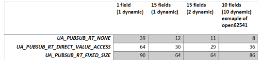
UA_PUBSUB_RT_NONE
Default "none-RT" Mode. For each DataSetField the value is read out of the information model. This is slowing down the publishing process.
UA_PUBSUB_RT_DIRECT_VALUE_ACCESS
Within this RT-mode, the value source of each field is configured as static pointer to a DataValue. The publish cycle is improved by prevent the value lookup within the information model. All fields must be configured with a static value source. The DataSetFields can still have a variable size. The published fields are not visible in the information model.
UA_PUBSUB_RT_FIXED_SIZE
All DataSetFields have a known, non-changing length. The server will pre-generate some buffers and use only memcopy operations to generate requested PubSub packages. The configuration must be frozen while it is operational. The published fields are not visible in the information model.
Design preparation
For the detailed design preparation steps please check the post OPC UA Server on a FPGA using open62541 and OPC UA PubSub on a FPGA using open62541.
Basic OPC UA Server PubSub application
In the Xilinx SDK the available OpcServer.c can be imported to the OpcServer application project.
In the basic server the thread stack size was defined with 4096. This is not enough anymore and the application will report with the hook functions a StackOverFlow. Therefore, the THREAD_STACKSIZE was increased to 16384.
In a first step the network initialization and the basic OPC UA Server configuration is done. Before the server starts, the PubSub specific setup is needed. The application is targeted to be compatible with the Pub/Sub format for the IIC TSN Testbed interoperability application.
With different defines the tested configurations can be selected.
Changes compared to the last version
For the new PubSub feature some changes compared to the previous version are needed.
On the open62541 repository are examples available how the new feature can be used. With the help of the following examples the OpcServer.c was extended.
https://github.com/open62541/open62541/blob/master/examples/pubsub/server_pubsub_publisher_rt_level.c
Beside some small cosmetic adjustments and some added defines to compile the different versions mainly three adaptations were needed. The first one is how the data set field is added (addDataSetField function), then how the data set value is updated (valueUpdateCallback) and the last one is the freeze of the writer group before publishing starts (UA_Server_freezeWriterGroupConfiguration).
addDataSetField / UA_Server_addDataSetField:
The field needs to be set as static value source and the value must be assigned. A dynamic node is not added as before because of the pointer assignment of the published value.
valueUpdateCallback:
The updates of the values is done here (Pointer to the value).
UA_Server_freezeWriterGroupConfiguration:
This must be done before the publishing starts (only for the RT modes). It means that no dynamic changes of the write group are possible anymore. Before any change can be done, publishing must be stopped and the command UA_Server_unfreezeWriterGroupConfiguration called.
Measurements
As already mentioned in the beginning, the tests are only focusing on how many frames can be published. For all tests the same pub sub message was used and the measurement was done over 180 seconds. The MicroBlaze Soft-Core is running on 100MHz. No other connections to the server (e.g. disconnect UA Expert) are established.
The measurement was done with three different payload configurations for the three different modes. The header was always the same (Timestamp deactivated).
1. 1 published variable, with 1 dynamic value (payload: 24 bytes)

2. 15 published variables, with 1 dynamic value (payload: 182 bytes)
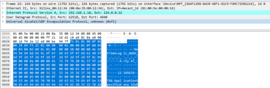
3. 15 published variables, with 2 dynamic values (payload: 182 bytes)
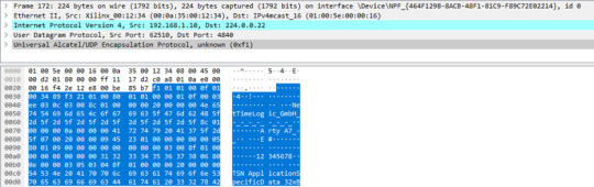
As a fourth frame format the example RT level PubSub application from open62541 was also tested. This has 10 published variables and all are dynamic (payload 80 bytes)

Measurement overview:

Observed problems with the RtLevel UA_PUBSUB_RT_FIXED_SIZE:
Header information update seems no to work as for the other modes (e.g Seq.-Nr).
With UA_UADPNETWORKMESSAGECONTENTMASK_TIMESTAMP enabled the dynamic value does not update anymore. Therefore, all tests were done without this flag. The reason was not investigated.
Summary
The RT level PubSub update of open62541 brings a substantial performance improvement already on a very low performant CPU. With the enhancement, also some limitations were added. Dynamic changes of the published Datasets are not possible while it is operational. This is most probably negligible for many applications. Another constraint of the RT level is that the values are not visible in the information model anymore. Updating the information model would decrease again the performance.
Especially the RT_FIXED_SIZE concept does show the benefit when many fields are published. It seems definitely as an option to use open62541 in combination with a Soft-Core in the FPGA. Of course, high-performance applications can’t be achieved, but for such cases usually a high perfmance CPU is anyhow already in place for the application part.
However, there are still some open points when it comes to dynamic fields of the header like timestamps or sequence number. There seems to be some remaining work (Updates in the header in the UA_PUBSUB_RT_FIXED_SIZE mode).
Some general updates in the header seems not to work as expected:
GroupHeader
GroupVersion was not assigned
SequenceNumber was not assigned
ExtendedNetworkMessageHeader
Timestamp was empty
For our testing we have done the same quick fix as described in the previous post.
As a next step the deterministic behavior will be the focus. Preferable already in combination with our TSN End Node.
0 notes
Text
Programming Assignment 1: An Introduction to Verilog Solution
Programming Assignment 1: An Introduction to Verilog Solution
Assignment
This assignment is meant to make sure that your development environment is working properly and to get you thinking about boolean logic, Verilog, and the process of digital logic design on an FPGA.
Take a look at the structural verilog guide on Canvas as well as the Verilog cheat sheet in the guides folder for help getting started with Verilog.
The main.v file defines a module with an…
View On WordPress
0 notes
Text
Programming Assignment 1: An Introduction to Verilog Solution
Programming Assignment 1: An Introduction to Verilog Solution
Assignment
This assignment is meant to make sure that your development environment is working properly and to get you thinking about boolean logic, Verilog, and the process of digital logic design on an FPGA.
Take a look at the structural verilog guide on Canvas as well as the Verilog cheat sheet in the guides folder for help getting started with Verilog.
The main.v file defines a module with an…
View On WordPress
0 notes
Text
Matlab Assignment Help | Matlab Project Help | Matlab Online Tutoring Help
Matab is a tool which is used to solve typical and length problems of different subjects like Electronics, Electrical, Civil, Mechanical Engineering, Finance, Bioinformatics, Mathematics and Statistics etc. Matlabassignmenthelp.com is hub of qualified and experienced experts from all over the world. Most of the experts are PHD holders in their respective subjects and they have excellent knowledge of their subjects. They are passed out from top most institutes from all over the world like Oxford, Cambridge, IIT and IISC etc.
Matlabassignmenthelp.com is a sister concern of AE&R; Society which is renowned for helping poor and illiterate students across the world basically in asia and africa. AE&R; Society providing quality education and assistance to poor students through online tutoring and assignment help. We charge minimal free from students in respect of providing assistance in their projects and assignments. We also provide online tutoring sessions for students who want to learn Matlab.
We provide help in the following topic in Embedded System using matlab:
Microcontrollers
FPGA Design
Monolithic Kernels
Ubiquitous computing
Digital Signal Processing
ASIC and FPGA solutions
Embedded software architectures
Interrupt controlled system
Microkernels and exokernels
C code for embedded matlab
Embedded Source Code Verification
Target independent or target optimized HDL code
In Matlabassignmenthelp.com you will get following advantages:
Qualified and experienced group of experts from all over the world.
24*7 online live support help for students.
Reasonable price for homework help, assignment help and project help assistance.
Secure payment process.
Full refund policy for students if student is not satisfied with expert.
Full confidentiality regarding student information and assignment or project.
Free correction or emendation support to students.
Delivery of assignment or project as per committed timeline.
Matlab has a wide range of applications as we have already seen and is used in several industries covering
Automotive
Biological Sciences
Biotech and Pharmaceutical
Chemicals and Petrochemical
Communications
Electronics
Earth, Ocean, and Atmospheric Sciences
Energy Production
Financial Services
Industrial Automation and Machinery
Medical Devices
Metals
Materials and Mining
Neuroscience
Railway Systems
Semiconductors
Software and the Internet.
0 notes